How to create a Use Case diagram in PlantUML
1. Try it in the browser
You can render PlantUML diagrams instantly in your browser with the PlantUML Playground — no Java or server install required. The examples below can be pasted directly into it.
2. Define the diagram
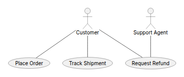
A use case diagram declares actors with actor Name and use cases with parentheses, either as Name as (Alias) or with a shorthand (Use case text). Connect an actor to a use case with a plain line -- to show it participates in that use case.
Here, Customer can place an order, track a shipment, or request a refund, and a Support Agent also participates in handling refunds.
3. Include, extend, and generalization
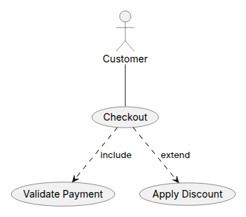
Use case diagrams support a few special relationships beyond a plain association:
| Relationship | Syntax | Meaning |
|---|---|---|
| Association | Actor -- (Use case) | The actor participates in / triggers the use case |
| Include | (A) ..> (B) : include | Use case A always performs the steps of use case B |
| Extend | (A) ..> (B) : extend | Use case A optionally adds behavior to use case B under some condition |
| Generalization | (A) <|-- (B) | Use case or actor B is a specialized variant of A (empty triangle arrowhead) |
4. System boundaries
Wrap related use cases in a rectangle "System name" { ... } block to draw a labeled boundary box around them, separating what the actors do from what the system provides:
The left to right direction statement is commonly used for use case diagrams so actors sit to the side of the system boundary rather than above it.
5. Render the diagram
Once you have defined the diagram, you can render it on your webpage with the @plantuml/core browser engine (the same one that powers this site's live editor), or by sending the markup to a PlantUML rendering server that returns an SVG image, the same way as shown on the PlantUML sequence diagram page.
You can use this PlantUML Playground Link to explore that particular example.